REX C100 teardown
 In true eevblog-style we take the REX C100 PID controller and don’t turn it on, but tear it apart.
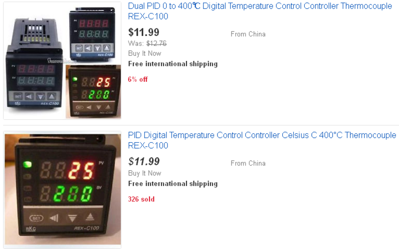
The controller can be found in many different options on eBay for around 10 Euro. I was curious to see what is inside this cheap PID controller so I opened it up and took some pictures to share.
Here’s how you typically find these controllers on eBay.
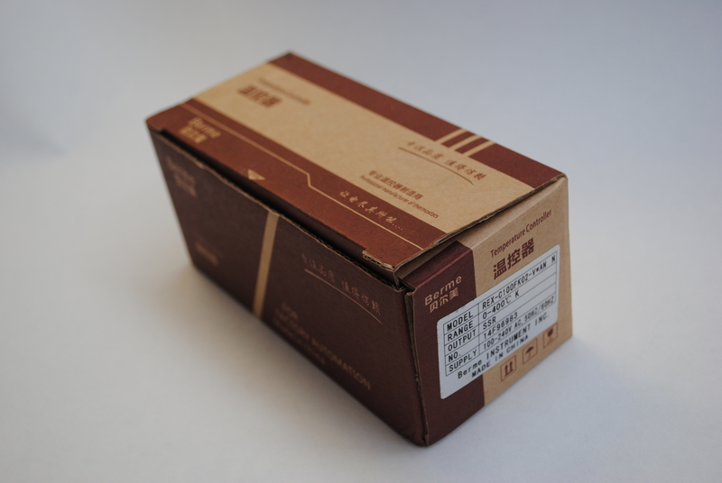
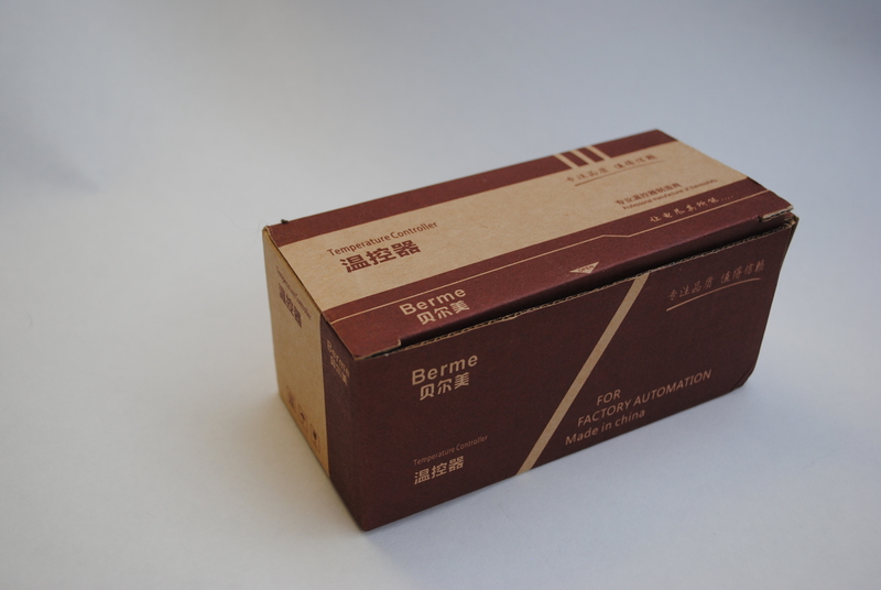
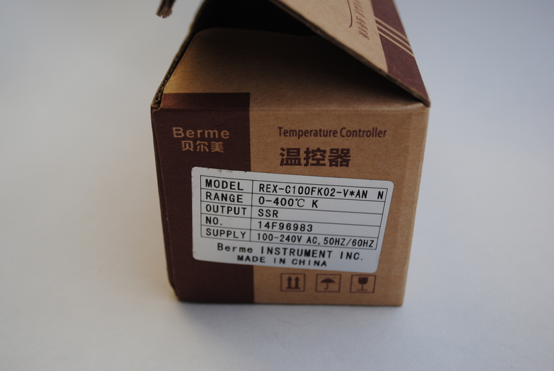
The REX C100 ships in a small cardboard box.

 These are the contents of the box as shipped: the controller itself (in a plastic cover), a plastic clip to lock it into the enclosure you wish to mount it in, and a user manual.
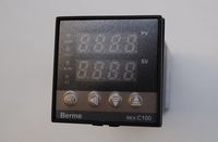
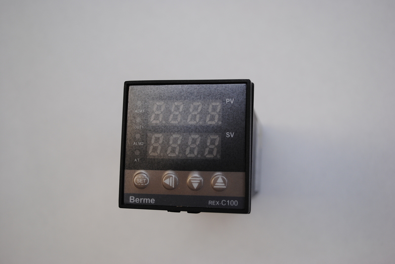 The front of the controller measures just 45x45mm (1.75x1.75”).
It has 2 4-digit 7-segment LED displays, one for the current temperature (process value or PV) and one for the set temperature (Set Value or SV). Next to these 2 displays are 4 LEDs, ALM1 (alarm 1, if present), OUT1 (output 1 actuated), ALM2 (alarm 2, if present) and AT (?).
Under the displays are 4 buttons, SET, LEFT, DOWN and UP.
The front also has the text “Berme REX C100” printed on the bottom.
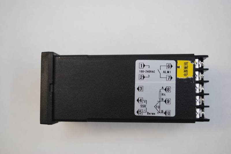 The right-hand side of the unit shows a wiring diagram for the terminals on the back.
Terminals 1 and 2 are the power input. The unit accepts both 110 and 240V AC power.
4 and 5 connect to the solid state relay (SSR) that controls the output. Mind the polarity here, as SSRs need to be hooked up with the correct polarity.
Terminals 6 and 7 have a dry relay contact for an alarm output.
Terminals 9 and 10 connect to a K-type thermocouple on my version of the REX C100.
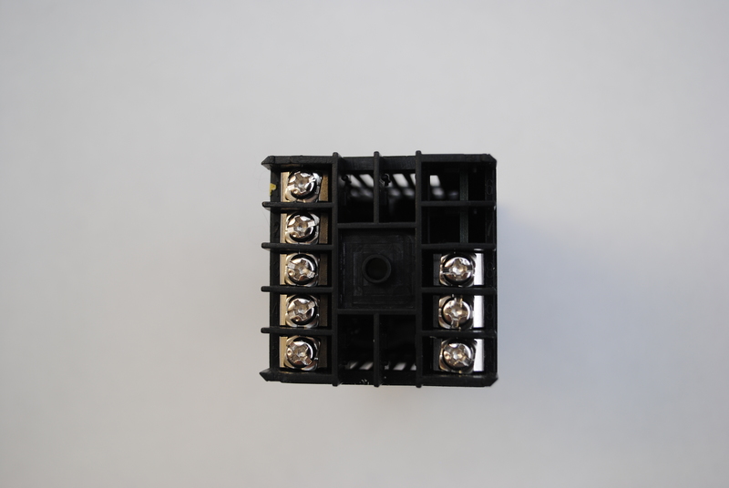 The terminals on the back are screw type. The screws accept both Philips and flat screw drivers. When connecting to these kind of terminals, the use of cable lugs is recommended.
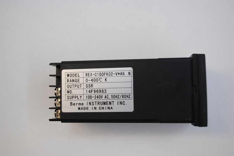 The left-hand side of the unit has a white sticker listing the the exact model number and specs of the unit.
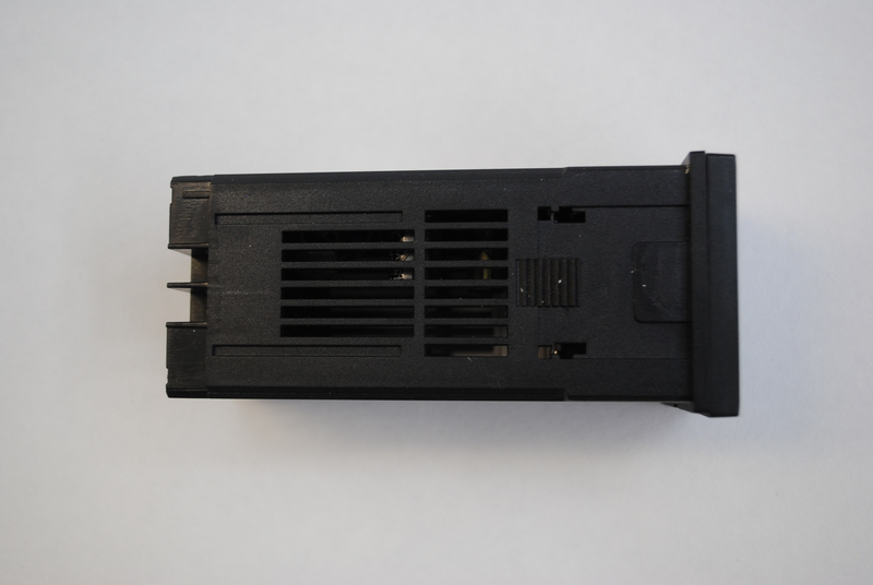 The top of the unit has similar ventilation slots.
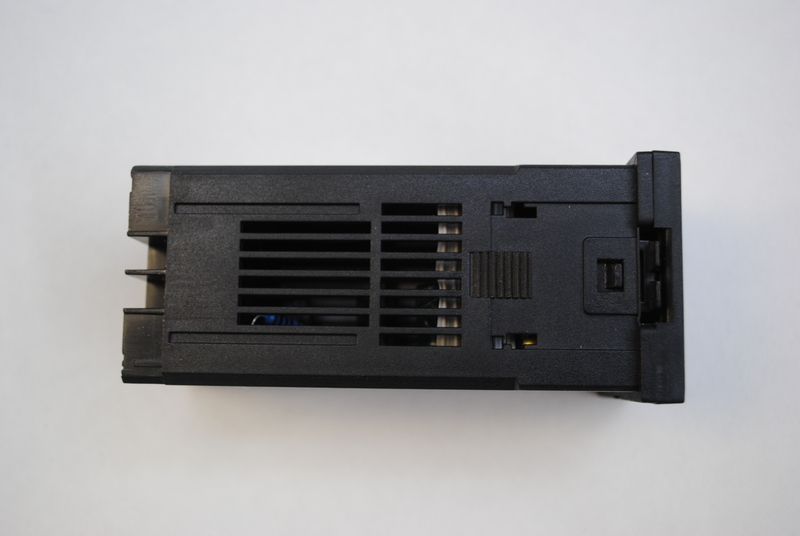 The bottom has slots for ventilation, and a tab near the front of the unit which opens the unit. When pushing in the two tabs near the front of the unit, the latch unlocks and allows the front display and attached PCBs to slide out of the unit in one piece.
 Here the latch is unlocked and the front display and PCBs are being slid out.
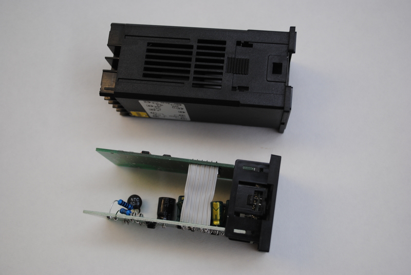 Here the internals have been fully slid out of the unit.
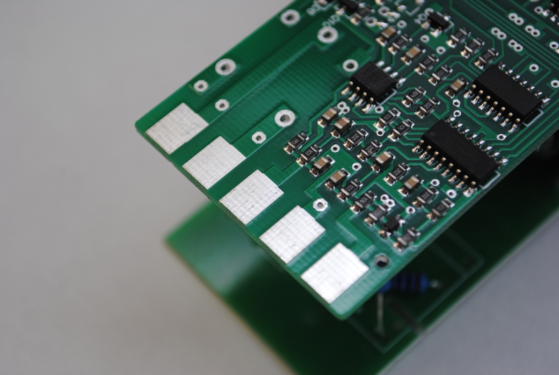
 Both PCBs have card edge-type pads on the back, which engage with the screw terminals on the back of the casing when the PCBs have been fully slid in.
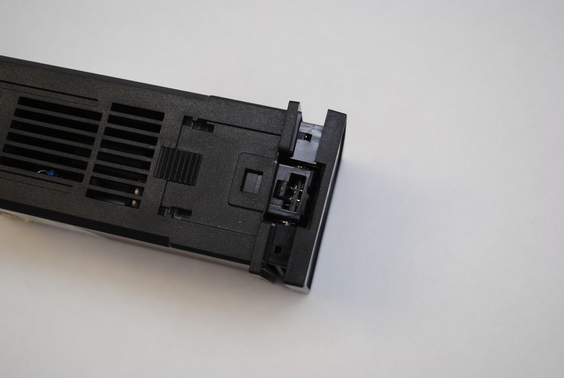
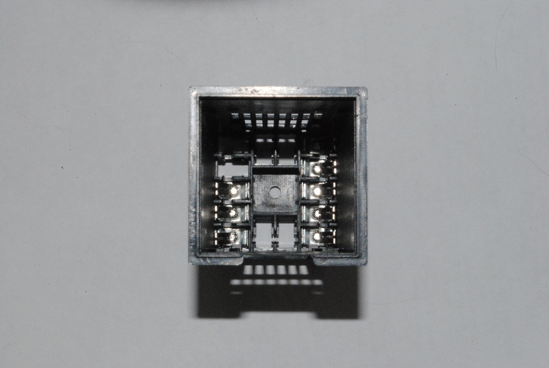 This picture shows the inside of the screw terminals which accepts the card edge connectors.
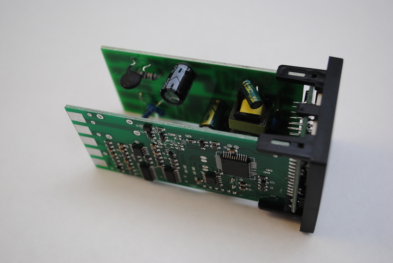
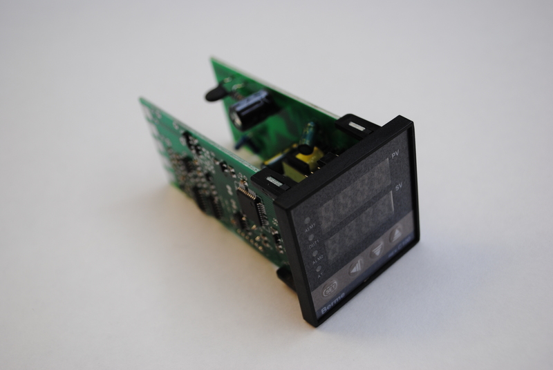 The controller’s internals consist of 3 PCBs; one that holds the displays, buttons and some associated logic on the front, and two PCBs that each hold the microcontroller circuitry and the power circuitry.
 The microcontroller PCB features an STC 89C52 microcontroller, which is an 8-bit 8051-based micro.
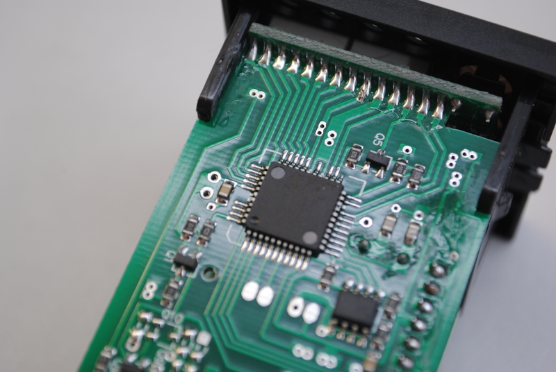 Detail of the STC 89C52 microcontroller (marked STC 89C52 35I-LQFP44G 1515652F90C).
 Next to the microcontroller (top right of this picture) is an SOIC-8 marked ATMLH436 02CM, which is an AT24C02C I2C-Compatible serial EEPROM, 2-Kbit (256 x 8). It is clocked by a crystal marked XJ11.0592.
The other chips on the board are:
- 74HC74D: dual positive edge triggered D-type flip-flop.
- HEF40518T: 8-channel analogue multiplexer/demultiplexer, which decodes 3 address lines into 8 outputs.
- LF353: Wide bandwidth Dual JFET Input Operational Amplifier. This opamp is used to measure the temperature using a PT100 or thermocouple.
The (unpopulated) rectangular footprint on the bottom left of the picture is for fitting the alarm relay. My REX C100 versions came without the alarm option, so the relay has been left unpopulated. The footprint is marked DC12V on the top of the PCB, so one could get an alarm signal from this footprint. The ground side of the relay is driven to ground through a transistor by the microcontroller in case of an alarm condition.
 Here’s a close-up detail of the card edge connector.
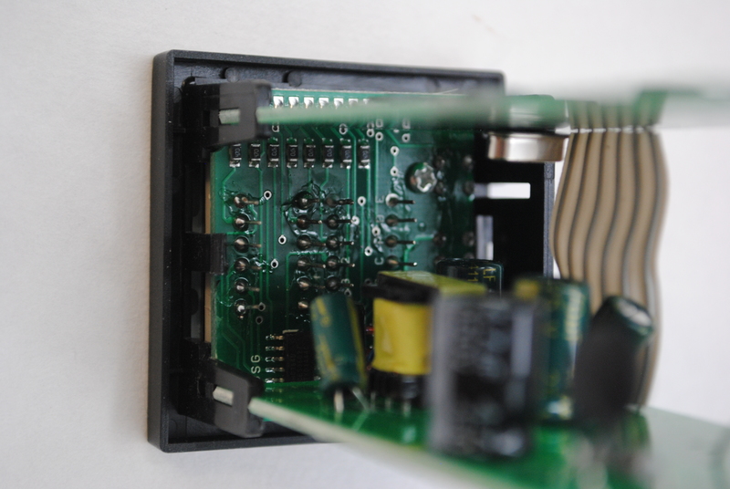
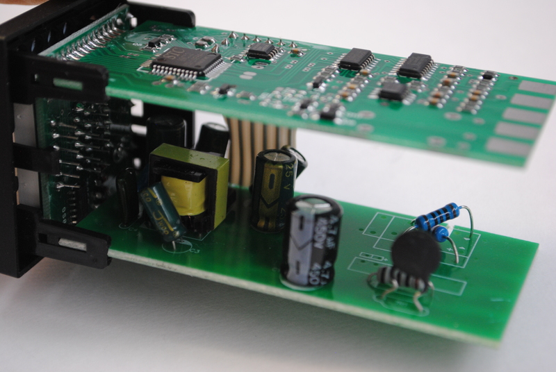 The two PCBs are connected by a 6-way ribbon cable which is soldered between the two boards (shown in the back).
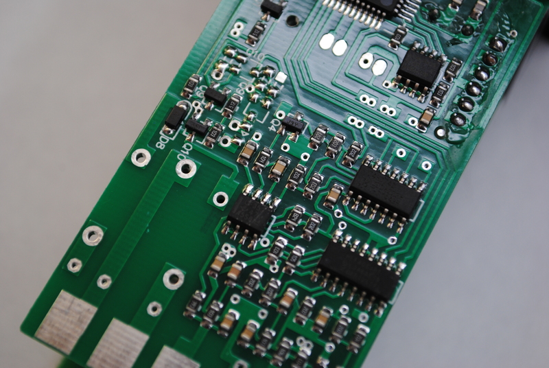
The bottom PCB mostly has a transformer and some caps on the top, and a few SMD components on the bottom. This hints at a power supply PCB.
What is interesting is the two-resistor arrangement on the back right. These resistors are placed over a footprint that can accept either of two different types of PCB-mount relays. The REX C100 PID controller is available with different output options; apparently the relay output versions have a relay populated, and the solid state relay versions have these two resistors to drive the SSR.
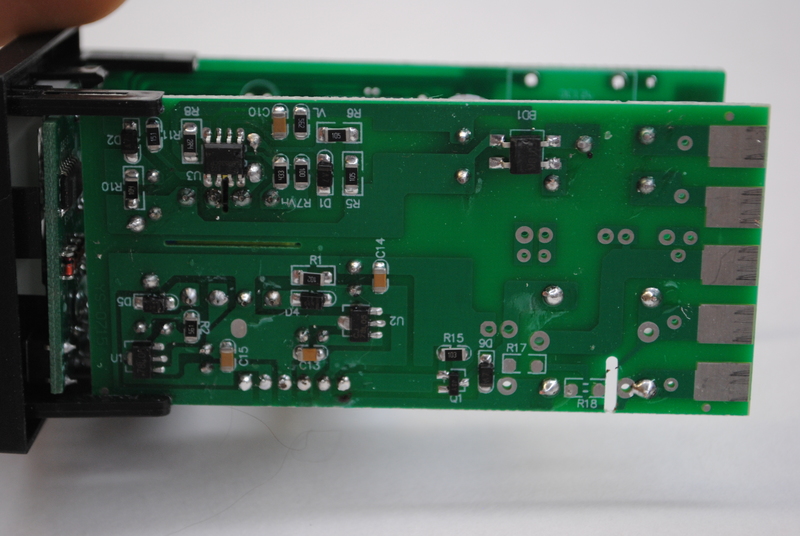 The bottom of the power supply PCB has an SOIC-8 chip marked 0B2535CP, which is “a high performance offline PWM Power switch for low power AC/DC charger and adaptor applications”.
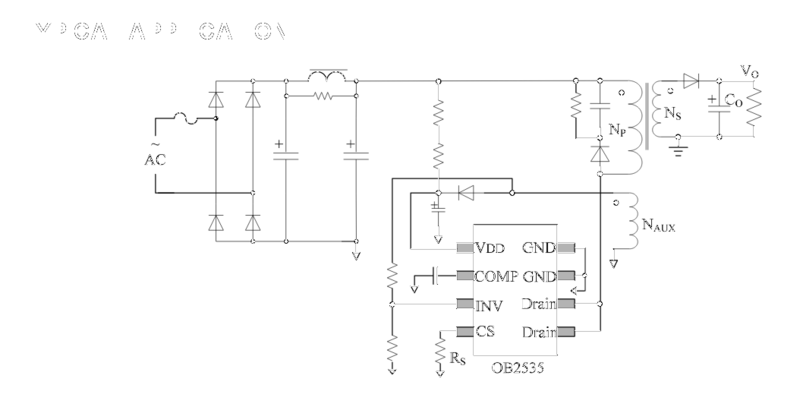 The typical application circuit shows a transformers, some diodes and caps. My bet is that the C100 uses the circuit mentioned in the datasheet.
Upstream from the 0B2535CP is a bridge rectifier marked MB103. Between this bridge rectifier and mains power are a resistor and what appears to be an NTC, marked NTC 5D-9, which apparently is a power NTC thermistor. Funny business. I guess the power supply section is one area where they had to cut costs.
Also on this board are two 78L05 linear regulators.
 The display board on the front of the unit is quite straight-forward. Either the rows or columns on the displays seem to be driven by a 74HC164 8-bit serial-in, parallel-out shift register. Most of the display pins are driven directly be the microcontroller however.